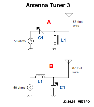

By using different amounts of inductance and capacitance, the antenna tuner can convert the antenna system impedance to 50 ohms for the radio. That’s where the antenna tuner comes to the rescue. So, if you want to load all your available power into the antenna system, you need to get the SWR at the transceiver below 1.5:1. It sounds complicated, but all the circuit does is reduce the radio’s output whenever it detects that the SWR has exceeded about 1.5:1. Transceiver manufacturers try to protect your radio from damage by including something called a foldback circuit. Suffice to say that an elevated SWR can be problematic for your radio.Īn elevated SWR can cause high voltages to appear in your transceiver’s output circuitry, and this is never a good thing. We explain SWR in the January/February 2021 issue (see “Untangling SWR”), so I won’t get into it here. If the antenna system impedance deviates too far from 50 ohms, the result is an elevated standing wave ratio, or SWR, at the radio. So instead, manufacturers design radios to deal with 50-ohm impedances at their outputs. They certainly could be more flexible, but that would add substantial cost - and physical size - to the radio. What’s the point of doing that? Well, modern transceivers are only designed to handle a narrow range of antenna impedances. When you reduce the function of an antenna tuner to the bare minimum, it’s as simple as this: It matches the impedance of the antenna system - measured in ohms - to the impedance the transceiver needs to see, which is 50 ohms.
#Images of an antenna tuner schematic how to#
In the January/February 2021 issue of On the Air, we spent several pages talking about antenna tuners, in the articles “Two Types of Antenna Tuner,” “Untangling SWR,” and “Antenna Tuners: Making a Match.” Here’s a closer look at how they work, how to buy one, and other considerations. If you would like to see a video on how this analyzer is used in conjunction with a transmatch to obtain a standing wave ratio of 1:1 and a purely resistive, non-reactive load, I have made one available on YouTube.By Steve Ford, WB8IMY, ARRL Contributing Editor If you understand the importance of adjusting antennas to appear purely resistive (non-reactive) to the transmitter at the frequency of operation, you can appreciate the significance of this instrument.

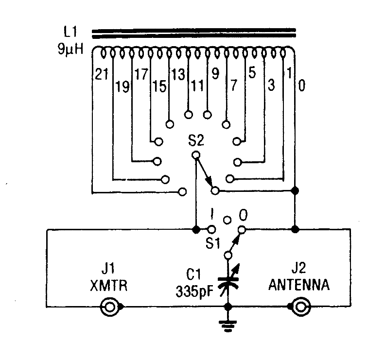
Using this device, the following antenna characteristics can be determined: standing wave ratio, resistance, impedance, and net reactance. I bought this in 2000 to help with the station antenna tuning and adjusting. Here is a slightly larger view of the MFJ-989C schematic.Ī variety of antennæ can be connected simultaneously, and switch-selected from the front panel.įinally, there is the analyzer. Its components are similar to those of the Signal Corps tuner seen above. When the analyzer is connected to the L-C tuner’s input and the Bird Termaline is connected to the tuner’s output, careful tuning of the tuner results in R = 50 ohms, X = 0 ohms, and SWR = unity regardless of the analyzer’s frequency setting, which comes as no surprise.Ī contemporary antenna tuner with internal instrumentation. Resistance equals 46 ohms, impedance equals 50 ohms, net reactance equals three ohms, and the SWR equals 1.1 to 1. Here is a typical reading with the analyzer connected directly to an actual forty-meter antenna. Schematic diagram of “The Ultimate Transmatch,” designed by Lew McCoy, W1ICP. This unit is probably capable of power levels up to 5,000 watts.


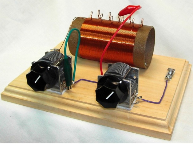
These tuners were used by the military during the Second World War. Roller inductor, split-stator input capacitor. Here are examples of how these goals can be accomplished, using either a military surplus L-C tuner or a commercially manufactured unit, along with an antenna analyzer that measures system performance, including load resistance and impedance, the standing wave ratio, and the net reactance at a particular frequency.Ī Bird Termaline dummy load, an MFJ-259B SWR Analyzer,Īnd an L-C tuner built from U.S. Nowadays with solid-state RF amplifiers in many of our contemporary rigs, good engineering practices and efficiency dictate we consider SWR and impedances in particular when it comes to maximum power transfer from the transmitter to the antenna, and minimum reflection from the antenna back to the transmitter. In those days our transmitters were equipped with vacuum tubes, which were relatively forgiving. We hung our antennas, and if they worked, we used them.” There is nothing wrong with that philosophy. We had never heard of standing wave ratios or impedance matching. The Ultimate Transmatch A lifelong friend of mine was fond of saying, “I was first licensed in 1939.


 0 kommentar(er)
